

Category Mining Equipment
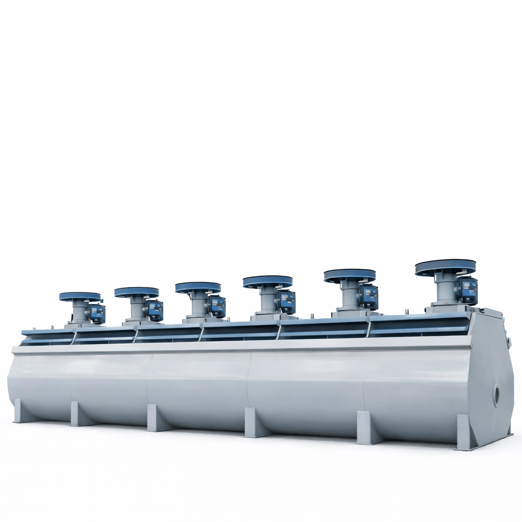
XCF/KYF Series Flotation Machine
The XCF/KYF Series Flotation Machine is an enforced aeration flotation system used for separating nonferrous metals, ferrous metals, and non-metallic minerals in mineral processing circuits.
Pricing Disclaimer: All pricing is subject to change and may be impacted by tariffs, duties, shipping rates, and international market conditions. Final pricing will be confirmed at the time of order placement and locked in once a purchase agreement is issued.
Share Product :
The XCF and KYF Series Flotation Machines are designed as enforced aeration flotation units commonly applied in mineral beneficiation operations. They are widely used across flotation circuits handling metallic and non-metallic ores where controlled aeration and stable particle suspension are required.
Both models operate together within the same circuit and share similar structural layouts and overall dimensions. Air is supplied externally and distributed evenly through an air distributor located within the tank, while the impeller functions as a centrifugal pump to keep solid particles uniformly suspended in the slurry.
This configuration supports lower power consumption by using a smaller-diameter impeller while maintaining effective mixing and air dispersion. The U-shaped tank design minimizes sand settlement, and the impeller geometry promotes even wear, which helps reduce reagent consumption and ongoing operating costs.
The machines are built to operate under load with a relatively simple mechanical structure, making them suitable for continuous-duty flotation applications. Integrated slurry level control further supports stable operation and simplifies day-to-day process control.
The XCF/KYF Series is best suited for operations processing a wide range of ore types that require consistent flotation performance, flexible capacity scaling, and reliable aeration control.
The technical data below outlines effective cell volume, physical dimensions, impeller size, motor power, air pressure requirements, airflow settings, slurry capacity, and single-cell weight to support equipment selection and circuit design.
If you are evaluating flotation equipment for a new plant or upgrading an existing circuit, we can help review sizing, configuration, and integration options based on your material characteristics and throughput requirements.
This table provides XCF/KYF Series Flotation Machine specifications, including effective volume, cell dimensions, impeller size, motor power, air pressure, airflow settings, slurry capacity, and single-cell weight.
| Model | Effective Volume (m³) | Dimension of Cell (L × W × H) (m) | Diameter of Impeller (m) | Power (kW) | Air pressure of the min air inlet (kPa) | Airflow setting (m³/㎡·min) | Capacity (m³/min) | Weight of Single Cell (kg) |
| XCFⅡ/KYFⅡ-1 | 1 | 1.00 × 1.00 × 1.00 | 0.40/0.34 | 4/3 | >11 | 0.05~1.4 | 0.2~0.5 / 0.2~1 | 920/1056 |
| XCFⅡ/KYFⅡ-2 | 2 | 1.30 × 1.30 × 1.25 | 0.47/0.41 | 5.5/4 | >12 | 0.05~1.4 | 0.5~1 / 0.5~2 | 1158/1346 |
| XCFⅡ/KYFⅡ-3 | 3 | 1.60 × 1.60 × 1.40 | 0.54/0.48 | 7.5/5.5 | >14 | 0.05~1.4 | 0.7~1.5 / 0.7~3 | 2172/2074 |
| XCFⅡ/KYFⅡ-4 | 4 | 1.80 × 1.80 × 1.50 | 0.62/0.55 | 11/7.5 | >15 | 0.05~1.4 | 1~2 / 1~4 | 2375/2100 |
| XCFⅡ/KYFⅡ-6 | 6 | 2.05 × 2.05 × 1.75 | 0.62/0.55 | 18.5/11 | >17 | 0.05~1.4 | 1~3 / 1~6 | 3545/3278 |
| XCFⅡ/KYFⅡ-8 | 8 | 2.20 × 2.20 × 1.95 | 0.72/0.63 | 22/15 | >19 | 0.05~1.4 | 2~4 / 2~8 | 4142/3857 |
| XCFⅡ/KYFⅡ-10 | 10 | 2.40 × 2.40 × 2.10 | 0.76/0.66 | 30/22 | >20 | 0.05~1.4 | 3~5 / 3~10 | 4894/4334 |
| XCFⅡ/KYFⅡ-16 | 16 | 2.80 × 2.80 × 2.40 | 0.86/0.74 | 37/22 | >23 | 0.05~1.4 | 4~8 / 4~16 | 6928/7545 |
| XCFⅡ/KYFⅡ-20 | 20 | 3.00 × 3.00 × 2.70 | 0.91/0.78 | 45/37 | >25 | 0.05~1.4 | 5~10 / 5~20 | 9200/8240 |
| XCFⅡ/KYFⅡ-24 | 24 | 3.10 × 3.10 × 2.90 | 0.93/0.80 | 55/37 | >27 | 0.05~1.4 | 6~12 / 6~24 | 10819/9820 |
| XCFⅡ/KYFⅡ-30 | 30 | 3.50 × 3.50 × 3.025 | 0.88/0.90 | 55/45 | >31 | 0.05~1.4 | 7~15 / 7~30 | 14810/13820 |
| XCFⅡ/KYFⅡ-40 | 40 | 3.80 × 3.80 × 3.40 | 1.05 | 75/55 | >32 | 0.05~1.4 | 8~19 / 8~38 | 18790/17097 |
| XCFⅡ/KYFⅡ-50 | 50 | 4.40 × 4.40 × 3.50 | 1.20/1.03 | 90/75 | >33 | 0.05~1.4 | 10~25 / 10~40 | 22000 |
| XCFⅡ/KYFⅡ-70 | 70 | Φ 4.30 × 4.10 | 1.12 | 90 | >35 | 0.05~1.4 | 13~50 | 26200 |
| XCFⅡ/KYFⅡ-100 | 100 | Φ 5.80 × 4.56 | 1.26 | 132 | >40 | 0.05~1.4 | 20~60 | 33500 |
| XCFⅡ/KYFⅡ-130 | 130 | Φ 6.50 × 4.90 | 1.30 | 160 | >45 | 0.05~1.4 | 20~60 | 36200 |
| XCFⅡ/KYFⅡ-160 | 160 | Φ 7.00 × 5.20 | 1.35 | 160 | >48 | 0.05~1.4 | 20~60 | 42500 |
Product Specification Disclaimer:
While Bros Dirt Diggers makes every effort to ensure product specifications and details are accurate, final equipment specifications are subject to manufacturer confirmation. Customers should verify all critical details before purchase.
Customize Your Own Crushing Plant Now
Fill your requirements here, and we’ll send the custmized solution and quotation to you by the reserved contact information.
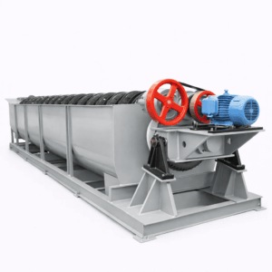
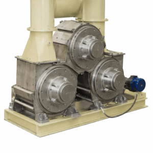
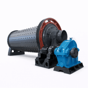
Related Product
Get in Touch
We’re always here to help with your equipment and plant needs.
Send Us a Message
Tell us what you’re working on — our team will help you find the right equipment or solution.
572V+75W Octave, Arizona, USA
Call Center 1
541-513-4542
541-513-4542
Call Center 2
480-241-2454
480-241-2454
brosdirtdiggersllc@gmail.com